Nguyễn Văn Thành, KP9 , Chánh Phú Hòa, Bến Cát, Bình Dương
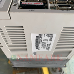
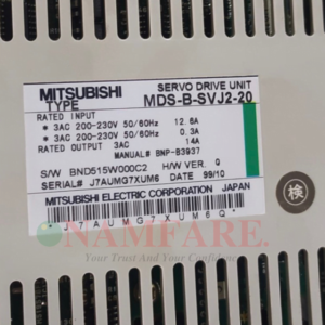
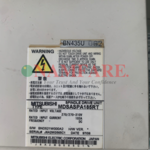
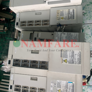
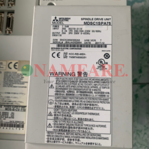
Bộ Điều Khiển Tay Dao Và Magazine MR J2 100 CT Mitsubishi Máy Mazak
HỖ TRỢ TRỰC TUYẾN
Kinh Doanh: 0937029193
Giờ Làm Việc: 8h đến 18h từ thứ 2 đến thứ 7.
Danh mục: Thiết Bị Điện
Mô tả
Technical description:
with UL/c-UL Standard (MDS-B-SVJ2, MDS-B-SPJ2 and MR-J2-CT Series) The instructions of UL/c-UL listed products are described in this manual. The descriptions of this manual are conditions to meet the UL/c-UL standard for the UL/c-UL listed products. To obtain the best performance, be sure to read this manual carefully before use. To ensure proper use, be sure to read specification manual carefully for each product before use.
1. Operation surrounding air ambient temperature The recognized operation ambient temperatures of each unit are as shown in the table below. The recognized operation ambient temperatures are the same as an original product specification for all of the units. Classification Unit name operation ambient temperature Power supply unit 0~55°C Servo drive unit 0~55°C Spindle drive unit 0~55°C Option unit 0~55°C Battery unit 0~55°C AC servo/ spindle system Servo motor, Spindle motor 0~40°C
2. Notes for AC servo/spindle system 2-1 General Precaution It takes 10 minutes to discharge the bus capacitor. (The capacitor discharge time is one minute for MDS-B-SVJ2-01, 03, 04; two minutes for MDS-B-SVJ2-06 and three minutes for MDS-B-SVJ2-07, 10, 20.) When starting wiring or inspection, shut the power off and wait for more than 15 minutes to avoid a hazard of electrical shock. 2-2 Installation MDS-B-SVJ2, MDS-B-SPJ2 and MR-J2-CT Series have been approved as the products which have been installed in the electrical enclosure. The minimum enclosure size is based on 150 percent of each MDS-B-SVJ2, SPJ2 and MR-J2-CT Series combination. And also, design the enclosure so that the ambient temperature in the enclosure is 55°C (131°F) or less, refer to the specifications manual. (MDS-B-SVJ2: BNP-B3937, MDS-B-SPJ2: BNP-B2164, MR-J2-CT: BNP-B3944) “The user must include the use of a 100 cfm fan spaced 4 in. above the drive.” 2-3 Short-circuit ratings Suitable for use in a circuit capable of delivering not more than 100 kA rms symmetrical amperes, 500 volts maximum. 2-4 Peripheral device To comply with UL/c-UL Standard, use the peripheral devices which conform to the corresponding standard. – Fuses Applicable drive unit UL Fuse type UL Voltage rating, Vac UL Current rating, A MDS-B-SVJ2-01 K5 250 10 MDS-B-SVJ2-03 K5 250 10 MDS-B-SVJ2-04 K5 250 15 MDS-B-SVJ2-06 K5 250 20 MDS-B-SVJ2-07 K5 250 20 MDS-B-SVJ2-10 K5 250 25 MDS-B-SVJ2-20 K5 250 40 MDS-B-SPJ2-02 K5 250 10 MDS-B-SPJ2-04 K5 250 15 MDS-B-SPJ2-075 K5 250 20 MDS-B-SPJ2-15 K5 250 40 MDS-B-SPJ2-22 K5 250 40 MDS-B-SPJ2-37 K5 250 60 MDS-B-SPJ2-55 K5 250 90 MDS-B-SPJ2-75 K5 250 125 MDS-B-SPJ2-110 K5 250 175 Applicable drive unit UL Fuse type UL Voltage rating, Vac UL Current rating, A MR-J2-10CT K5 250 10 MR-J2-20CT K5 250 10 MR-J2-40CT K5 250 15 MR-J2-60CT K5 250 20 MR-J2-70CT K5 250 20 MR-J2-100CT K5 250 25 MR-J2-200CT K5 250 40 MR-J2-350CT K5 250 70 – Circuit Breaker for of spindle motor Fan Select the Circuit Breaker by doubling the spindle motor fan rated. A rush current that is approximately double the rated current will flow, when the fan is started – For installation in United States, branch circuit protection must be provided, in accordance with the National Electrical Code and any applicable local codes. – For installation in Canada, branch circuit protection must be provided, in accordance with the Canada Electrical Code and any applicable provincial codes. 2-5 Motor Over Load Protection Servo drive unit MDS-B-SVJ2, MDS-B-SPJ2 and MR-J2-CT series have each solid state motor over load protection. (The motor full load current is the same as rated current.) When adjusting the level of motor over load, set the parameter as


