Nguyễn Văn Thành, KP9 , Chánh Phú Hòa, Bến Cát, Bình Dương


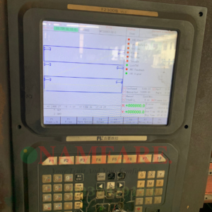
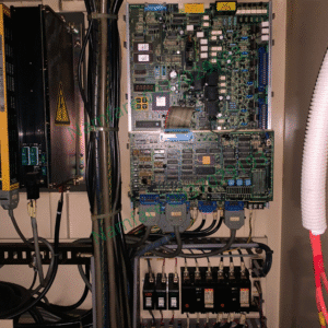
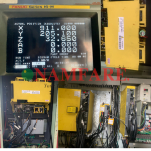
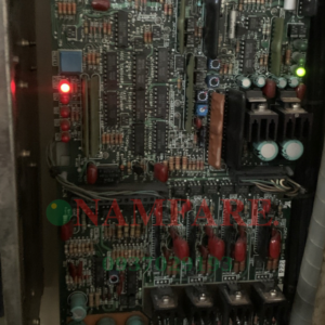
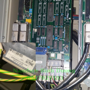
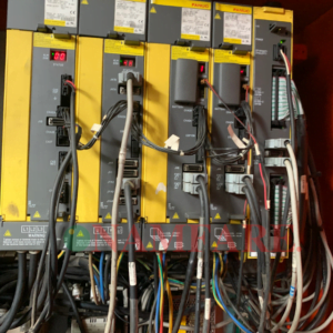
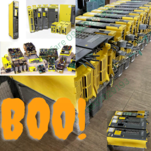
Sửa chữa bo mạch Fanuc lỗi Al 02, Al 08, HV, HC, LV Spindle Drive Servo Amplifers
Mô tả
Các lỗi máy CNC
Mã lỗi AC Spindle Fanuc đời A06B-6055-Hxxx | Nội Dung Các Mã Lỗi Trên Drive |
| AL-01 | Motor Overheated |
| AL-02 | Speed deviates from commanded speed |
| AL-03 | Fuse F7in DC link is blown out. |
| AL-04 | Fuses F1,F2,F3 for AC input blown out. |
| AL-06 | Excess Motor Speed Analog |
| AL-07 | Excess Motor Speed Digital |
| AL-08 | Voltage higher than specified (24v) |
| AL-09 | Radiator for power semiconductor overheat |
| AL-10 | +15v power supply is abnormally low |
| AL-11 | DC Link voltage is high |
| AL-12 | DC Link current is high |
| AL-13 | Data memory for CPU abnormal |
| AL-16 | RAM in NVRAM is abnormal |
| AL-17 | ROM in NVRAM is abnormal |
| AL-18 | Check sum alarm of ROM |
| AL-19 | Excessive alarm of U phase current detection circuit offset |
| AL-20 | Excessive alarm of V phase current detection circuit offset |
| AL-21 | Excessive alarm of velocity command circuit offset. |
| AL-22 | Excessive alarm of velocity detection circuit offset. |
| AL-23 | Excessive alarm of ER circuit offset. |
| AL-14 | ROM is abnormal |
| AL-15 | Spindle selection control circuit is abnormal. |
Các lỗi về bộ điều khiển khác
Mã lỗi AC Spindle Fanuc đời A06B-6059-Hxxx | Nội Dung Các Mã Lỗi |
| AL-01 | Motor Overheat |
| AL-02 | Speed deviates from commanded speed |
| AL-03 | 24v Fuse is blown. (before PCB edition 09A) |
| AL-04 | Fuses F1,F2,F3 for AC input blown out. |
| AL-06 | Excess Motor Speed Analog |
| AL-07 | Excess Motor Speed Digital |
| AL-08 | Over voltage |
| AL-09 | Overheat of radiator |
| AL-10 | Low voltage of input power. |
| AL-11 | Excessive high voltage of DC link |
| AL-12 | Abnormal current of DC link |
| AL-15 | Spindle selection control circuit is abnormal. |
| AL-16-23 | Defective arithmetic circuit and peripheral circuit |
| No indication | Defective ROM |
Các Lỗi Về Program P/S Alarms
| Mã Lỗi | Nội Dung Các Mã Lỗi |
| 000 | A parameter which requires the power off was input, turn off power. |
| 001 | TH alarm ( A character with incorrect parity was input. Correct the tape. |
| 002 | TV alarm ( The number if characters in a block is odd). This alarm will be generated only when the TV check is effective. Correct the tape. |
| 003 | Data exceeding the maximum allowable number of digits was input. (Refer to the item of max.programmable dimensions) |
| 004 | A numeral of the sign “-” was input without an address at the beginning of a block. |
| 005 | The address was not followed by the appropriate data but was not followed by another address or EOB code. |
| 006 | Sign “-” input error ( Sign “-” was input after an address with which it cannot be used. Or two or more “-” signs were input) |
| 007 | Decimal point “-” input error. |
| 009 | Unusable character was input insignificant area. |
| 010 | An unusable G code was commanded. |
| 011 | Feedrate was not commanded to a cutting feed or the feedrate was inadequate. |
| 014 | In variable lead threading the lead incremental and decremental outputted by address K exceed the maximum command value or a command such that the lead becomes a negative value is given. |
| 015 | The number of the commanded axes exceeded that of simultaneously controlled axes. |
| 021 | An axis not included in the selected plane was commanded in circular interpolation. |
| 023 | In circular interpolation by radius designation negative value was commanded for address R. |
| 029 | The offset value is too large. |
| 030 | The offset number specified by * code for tool length offset (or cutter compensation is too large.) |
| 031 | In setting an offset amount by G10, the offset number following address P was excessive or it was not specified. |
| 032 | In setting an offset amount by G10, the offset amount was excessive. |
| 033 | A point of intersection cannot be determined for cutter compensation C/ Tool nose radius compensation. |
| 034 | The start up or cancel was going to be performed in the G02 or G03 mode in cutter compensation C/tool nose radius compensation. |
| 035 | G39 is commanded in cutter compensation B cancel mode or on the plane other than offset plane/Ship cutting (G31 was specified in tool nose radius compensation mode. |
| 036 | Skip cutting (G31) was specified in cutter compensation mode. |
| 037 | G40 ( offset cancel) is commanded at the plane other than the offset plane in cutter compensation B. The plane selected by using G17, G18, G19 is changed in cutter compensation C mode. |
| 038 | Overcutting will occur in cutter compensation C because the arc start point or end point coincides with the arc centre/Overcutting will occur in tool nose radius compensation C because the arc start point or end point coincides with the arc centre/ |
| 039 | Chamfering or corner R was specified with a start up, a cancel, or switching between G41 and G42 in tool nose radius compensation. The program may cause overcutting to occur in chamfering or corner R. |
| 040 | Overcutting will occur in tool nose radius compensation in a canned cycle G90 or G94. |
| 041 | Overcutting will occur in cutter compensation C/ tool radius compensation. |
| 044 | One of G27 to G30 is commanded in canned cycle mode. |
| 050 | The chamfering or a corner R was specified in a block which includes a thread cutting command. |
| 051 | The block after a block containing a chamfering or a corner R specification was not a G01 command. |
| 052 | The move direction or the move amount in a block following chamfering or a corner R command was not adequate. |
| 053 | 2 or more of I, K and R are directed in chamfering and corner radius R command or C or R does not come after a comma (,) in direct drawing dimension programming. |
| 054 | A block in which the chamfering or the corner R was specified includes a taper command. |
| 055 | The move distance in the block which includes the chamfering or the corner R specification is smaller than the chamfering amount |
| 056 | Both end point and angle are not designated in the next block command of the angle designation block (A_). I (K) is commanded to X axis ( Z axis) in chamfering command. |
| 057 | Block end point is not calculated correctly in direct dimension drawing programming. |
| 058 | Block end point is not found in direct dimension drawing programming. |
| 059 | The program with the selected number cannot be searched in external program number search. |
| 060 | Commanded sequence number was not found in the sequence number search. |
| 061 | Address P or Q is not specified in G70, G71, G72 or G73 command. |
| 062 | The depth of cut in G71 or G72 is zero or negative value.The repetitive count in G73 is zero or negative value.The negative value is specified to A1 or Ak in G74 or G75. A value other than zero is specified to Ad, though the relief direction in G74 or G75 is determined. Zero on a negative value is specified to the height of thread of depth of cut of 1st time in G76. The specified minimum depth of cut in G76 is greater than the height of thread. An unusable angle of tool tip is specified in G76. |
| 063 | The sequence number specified by address P in G70, G71, G72 or G73 command cannot be searched. |
| 065 | G00 or G01 is not commanded at the block with the sequence number which is specified in address P in G71, G72 or G73 command.Address Z (W) or X (U) was commanded in the block with a sequence number which is specified by address P in G71 or G72 respectively. |
| 066 | An allowable G code was commanded between two blocks specified by address P and Q in G71, G72, G73. |
| 067 | G70, G71, G72 or G73 command with address P and Q was specified in MDI mode. |
| 069 | The final move command in the blocks specified by P and Q of G70, G71, G72 and G73 ended with chamfering or corner R. |
| 070 | The memory area is insufficient. |
| 071 | The address to be searched was not found. Or the program with specified program number was not found in program number search. |
| 072 | The number of programs to be stored exceeded 63 or 125. |
| 073 | The commanded program number has already been used. |
| 074 | The program number is other than 1 to 9999. |
| 076 | Address P was not commanded in the block which includes an M98 or a G65 command. |
| 077 | The subprogram was called in three or five folds. |
| 078 | A program number or a sequence number which was specified by address P in the block which includes an M98, M99 or G66 was not found. |
| 079 | The contents of the program stored in the memory did not agree with that in tape in collection. |
| 080 | In the area specified by parameter E, the measuring position reach signal does not come on. |
| 081 | Automatic tool compensation was specified without a T code. |
| 082 | T code and automatic tool compensation were specified in the same block. |
| 083 | In automatic tool compensation an invalid axis was specified or the command is incremental. |
| 085 | When entering data in the memory by using ASR or Reader/puncher interface , an overrun, parity or framing error was generated. The number of bits or input data or setting of baud rate is incorrect. |
| 086 | When entering data in the memory by using Reader/puncher interface , the ready signal (DR) of reader/puncher was turned off/. |
| 087 | When entering data in the memory by using Reader/puncher interface , though the read terminate command is specified input is not interrupted after 10 characters read. |
| 090 | The reference point return cannot be performed normally because the reference point return start point is too close to the reference point or the speed is too slow. |
| 092 | The commanded axis by G27 did not return to the reference point. |
| 094 | P type cannot be specified when the program is restarted. |
| 095 | P type cannot be specified when the program is restarted. |
| 096 | P type cannot be specified when the program is restarted. |
| 097 | P type cannot be specified when the program is restarted |
| 098 | A command of the program restart was specified without the reference point return operation after power ON and emergency stop and G28 was found during search. |
| 099 | After completion of search in program restart, a move command is given with MDI. |
| 100 | Setting data PWE is set to 1. Turn it to 0 and reset the system. |